STICKER Input
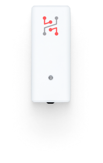
STICKER Input is a compact, wireless LoRaWAN module for connecting external sensors and reading digital or analog signals. Powered by two AA batteries, it supports 1-Wire temperature probes and the MACHINE PROBE, and its two external inputs work as digital inputs, 0–24 V analog inputs or S0 pulse counters, making it a versatile tool for industrial and monitoring applications.
Quick Links
- Getting Started Guide: Step-by-step setup guide.
- Buy STICKER Input: Purchase from our store.
- Ordering Codes: List of components and part numbers.
- Hardware Description: Technical details and hardware overview.
- Official Product Page: Features and overview.
Typical use cases
Smart temperature monitoring
- Some manufacturing processes require temperature monitoring across extreme ranges that conventional electronics can’t handle. External sensors, like 1-Wire temperature probes, are essential in such cases. A single data line can connect up to four sensors, enabling detailed and scalable monitoring.
Digitizing legacy machines
- Digitizing older machines can be tricky, even if they still run reliably. Many offer a 24 V digital output, or you can add an inductive sensor near the output mechanism to detect each produced item. This enables simple piece counting via digital signals.
Smart open/close detection
- Door and window detection isn’t just for security: it’s also key for smart heating and cooling. Traditional systems can be costly due to strict certification standards. STICKER Input offers a simple and affordable alternative with a built-in magnetic field sensor or digital inputs for standard switches.
Configuration and Wiring of External Inputs
Documentation → STICKER Input Wiring
Here you can find information about STICKER input wiring, including DIP switch settings and supported modes such as 1-Wire sensors, dry contact inputs, S0 pulse counters and 0–24 V analog inputs.
Example JSON Message
A periodic report as decoded by the v2.0.0 ttn.js decoder (fPort 2). In this example input A is a digital input with its pulse count, input B is an analog input (voltage in V) and 1-Wire slot 1 holds a Dallas DS18B20 probe. An input in pulse mode sends input_a_count / input_b_count and an input_a_is_active / input_b_is_active that is always false; an analog input sends only input_a_voltage / input_b_voltage.
Show JSON Example
{
  "voltage": 3.01,
  "boot": false,
  "alarm_status": 0,
  "alarm_status_flags": [],
  "temperature": 23.65,
  "humidity": 54,
  "input_a_count": 120,
  "input_a_is_active": true,
  "input_b_voltage": 12.35,
  "w1_sensors": [
    {
      "slot": 1,
      "type": 2,
      "type_name": "dallas",
      "values": { "temperature": 21.5 },
      "units": { "temperature": "degC" }
    }
  ]
}
Status LED
STICKER Input uses the standard status LED patterns described in LED Indication. The boot carousel, the status heartbeat every 3 seconds, and the NFC and alarm patterns are identical across all STICKER applications.
Because this application is the one that actually uses the digital inputs and Hall sensors, it is where the input activation indication matters most. These inputs report both directions, so the color order tells you which edge occurred:
| Event | Pattern |
|---|---|
| Input becomes active (contact closes, magnet approaches) | Green, then orange |
| Input returns to inactive (contact opens, magnet leaves) | Orange, then green |
This makes it possible to verify wiring and DIP switch settings on site without a console or a network connection: trigger the input and watch the order of the two colors.
An input in pulse mode (S0) has no state, so counted pulses show only the green-then-orange sequence. The LED blinks at most once every 0.5 s, so fast pulses do not each get a blink of their own. An analog input does not blink at all.
Input blinking is a commissioning aid and stops one hour after power-up. Counting and reporting continue as normal. Power-cycle the unit if you need the visual confirmation back while testing.
Changelog
2026-10-19 – v2.0.0
cap-gpio-mode inputstogether withcap-gpio-input-a/cap-gpio-input-bselects the mode of each external input:digital,analogorpulse; they replace the oldcap-input-a/-bflags, which are not carried over by the upgradeanalogmeasures 0–24 V on the input; the value can be sent in telemetry, recorded in the history and used in threshold alarmspulseis a pulse counter for S0 meter outputs (either polarity, 20 ms debounce)- Each 1-Wire slot stores the sensor type it expects (
sensor1-type…sensor4-type:2Dallas,3MACHINE PROBE); a different sensor in the slot raises asensor_mismatchalarm - A 1-Wire probe plugged in after power-up into a slot that waits for it (a stored ROM or
sensorN-type) is found without a reboot: the bus is checked 2 minutes after boot, then after another 5 and 10 minutes, then every 15 minutes - Every channel of a 1-Wire probe can be used in alarm rules and recorded in the history; a MACHINE PROBE with a failed accelerometer still measures temperature
2025-11-23 – v1.0.0
- Initial release: digital inputs, pulse counting, 1-Wire temperature probes, and analog measurement via LoRaWAN
For a complete overview of all platform changes, see the STICKER Changelog.